What is a hydraulic buffer
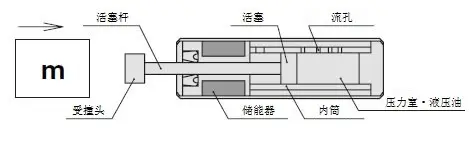
A buffer that mainly uses hydraulic oil. Compared with other buffer materials (rubber, spring, air, etc.), it can absorb large impact energy slowly and repeatedly with a compact shape without rebounding large impact energy. The internal structure and basic principles of the hydraulic shock absorber are described below.
· If an object strikes the piston rod, the hydraulic oil in the pressure chamber is compressed by the piston.
· The gap between the inner cylinder and the piston is very small, so the compressed hydraulic oil is sprayed out from the flow hole. Buffer It is precisely using the dynamic pressure impedance at this time to The impact energy is converted into heat energy.
· Because the piston rod is embedded in the main body of the buffer, only the hydraulic oil in the volume expansion portion of the piston rod causes the energy accumulator to shrink.
· Through the above operating principle, ideal impact absorption is achieved.
· By changing the number and size of the flow holes, a variety of absorption characteristics can be achieved. (See classification of structures based on absorptive properties)
· When selecting a buffer, if you select the wrong collision speed, ideal collision absorption will not be possible. When a collision occurs, abnormal reaction force may occur, and the collision energy may not even be absorbed, so please be careful.
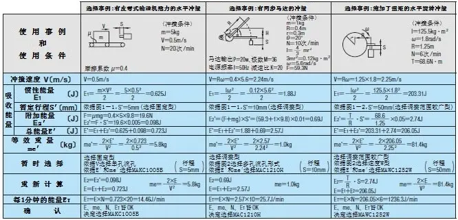
Select Step
① Calculation of inertial energy (E1)
According to the selected case, calculation is performed based on the weight of the collision object (m), collision velocity (V), inertial momentum (I), and collision angular velocity (Ω).
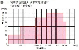
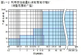
② Temporary buffer stroke
According to Figure 1-1 and Figure 1-2, obtain the tentative stroke (S’).
③ Calculation of additional energy (E2’)
Check to see if there is a driving force (F), and calculate the additional momentum according to the selected calculation case.
④ Calculation of total energy
Use inertial energy (E1) + additional energy (E2’) to calculate the total energy.
⑤ Confirm equivalent weight
According to the selected calculation example, calculate the equivalent weight and check whether it is below the maximum equivalent weight (me’) value in the product catalog.
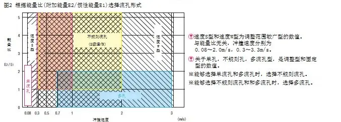
⑥ Select the absorption characteristic structure according to the energy ratio
According to Figure 2, temporarily select the flow hole form.
Select calculation case
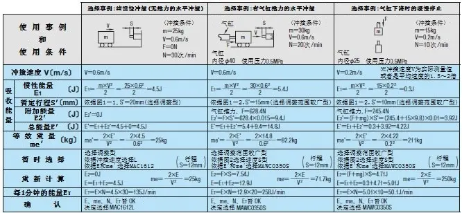
※In the case of pure inertial collision, the orifice form is selected based only on the collision speed.
Buffers take advantage of absorption properties Structure classification
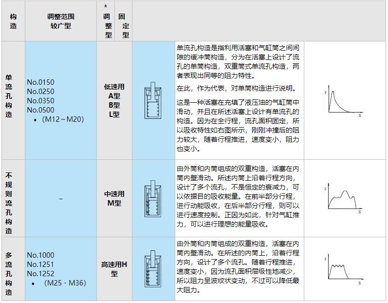
* Adjustment type No.0806M has a single orifice structure, and Type No.3625L has a multi-orifice structure.